اخبار صنعت
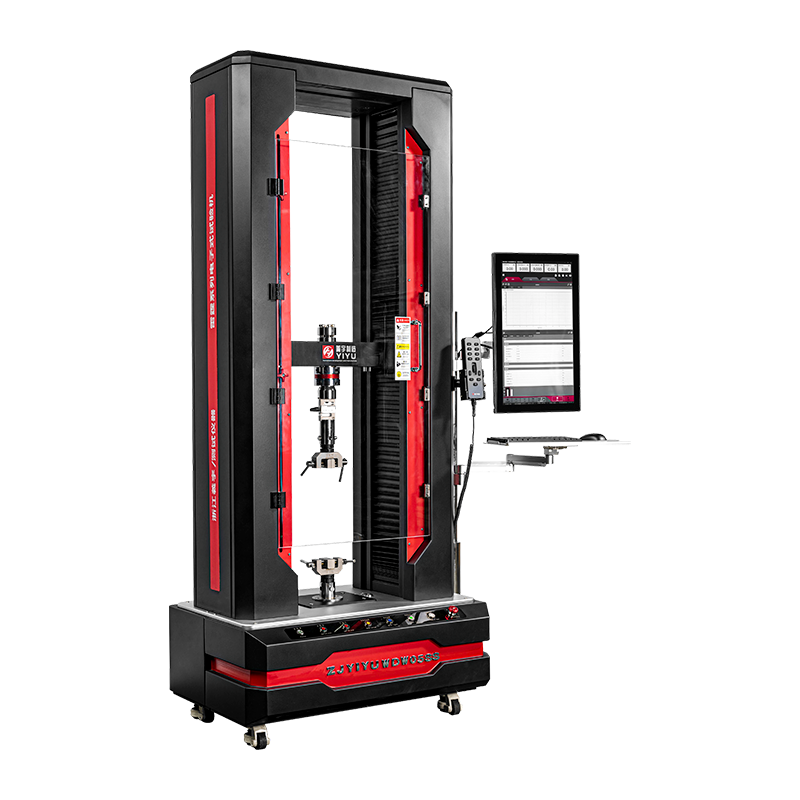
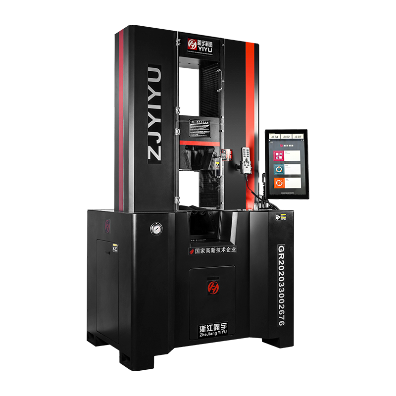
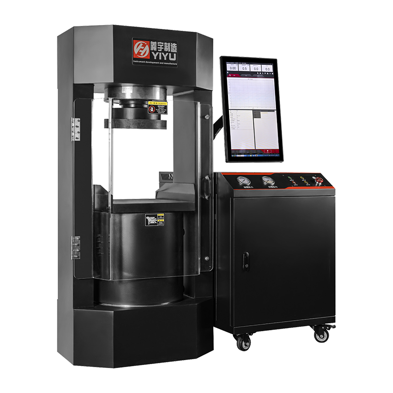
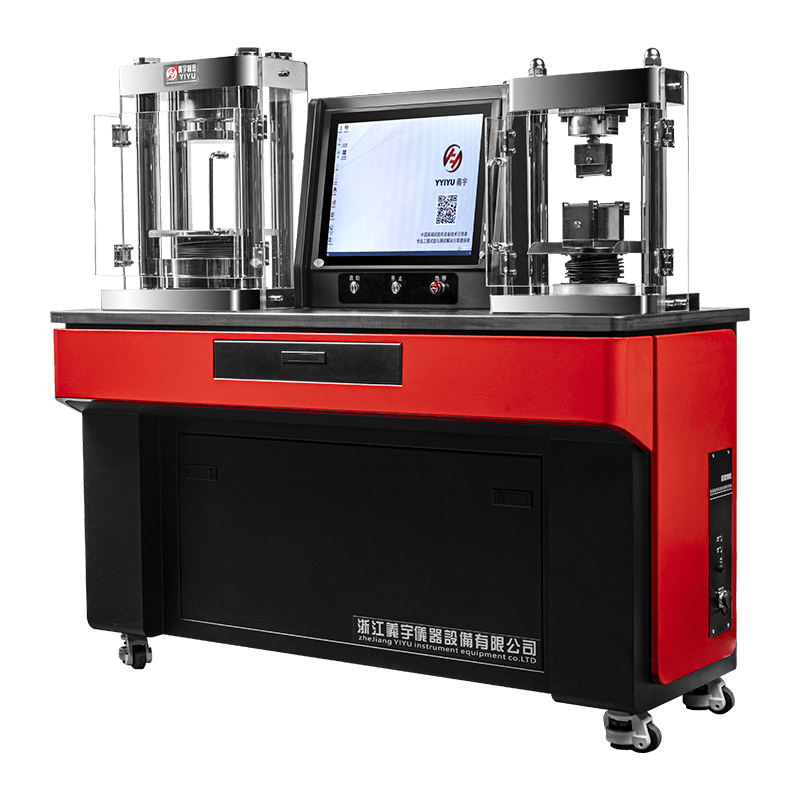
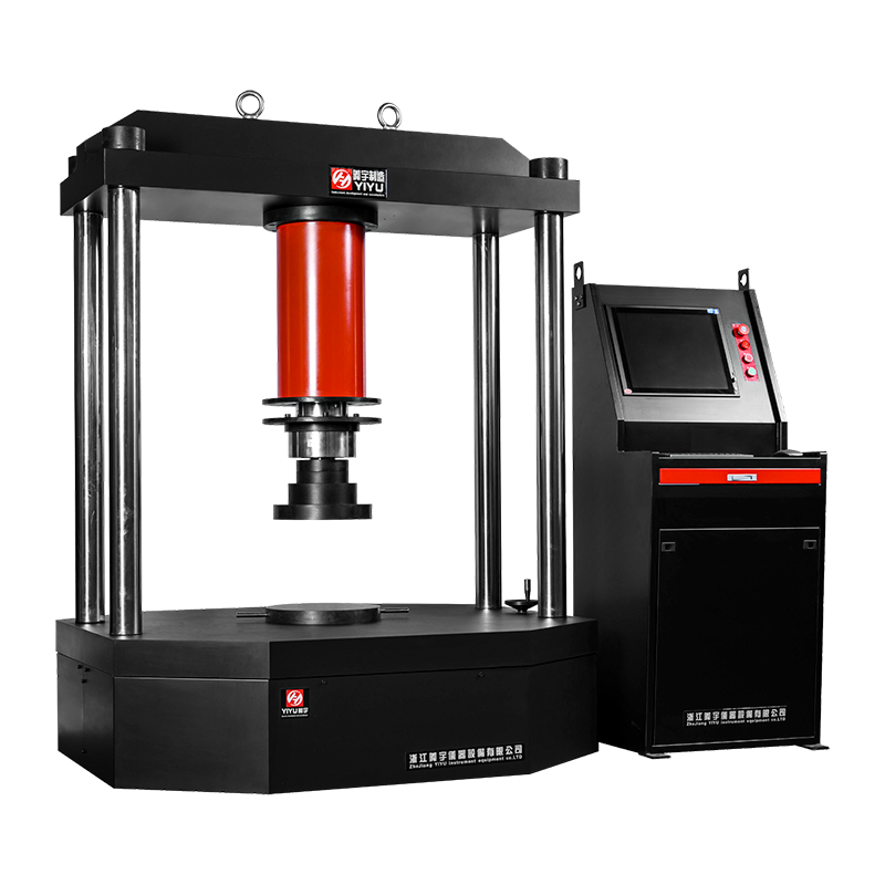
A universal testing machine (UTM) measures the mechanical properties of materials — including tensile strength, compressive strength, flexural strength, and elongation — by applying controlled forces and recording the material's response. To use one correctly, you must select the right machine type (electronic or hydraulic), install the appropriate grips or fixtures, set test parameters in the software, zero the load and extension, then run the test while monitoring the load-displacement curve in real time. This guide covers every step for both electronic and hydraulic UTMs, with practical data and comparisons to help you get accurate, repeatable results.
Choosing the correct machine type is the first and most consequential decision. Using the wrong platform can produce inaccurate data or even damage specimens and equipment.
| Feature | Electronic UTM | Hydraulic UTM |
|---|---|---|
| Typical force range | 0.5 N – 600 kN | 50 kN – 3,000 kN+ |
| Speed control | Precise (servo motor, ±0.5%) | Good (servo valve, ±1–2%) |
| Best for | Polymers, composites, thin metals, medical devices | Steel, concrete, heavy structural components |
| Noise & maintenance | Low noise, minimal upkeep | Louder, requires fluid checks |
| Displacement resolution | Up to 0.001 mm | Typically 0.01 mm |
| Energy consumption | Lower | Higher (hydraulic pump running continuously) |
As a practical rule: if your specimen requires more than 600 kN of force, choose a hydraulic UTM. For precision low-force work — such as testing a 0.2 mm polymer film or a biomedical suture — an electronic UTM with a 10 N load cell will yield far more meaningful data.
Regardless of machine type, every UTM shares the same core components. Misidentifying or misusing any one of them is a leading cause of invalid test results.
The structural backbone that holds all forces during the test. Frames are rated by their maximum load capacity. Never exceed 80% of the rated frame capacity in routine testing to avoid fatigue damage to the frame over time.
The force transducer that converts mechanical force into an electrical signal. Load cells have their own capacity ratings — for example, a 1 kN load cell installed on a 100 kN frame means the machine is effectively limited to 1 kN for that configuration. Always match the load cell to within 20–100% of the expected peak force of your specimen. Using a 100 kN load cell to test a specimen that breaks at 50 N will give unreliable readings.
In electronic UTMs, the crosshead is driven by a precision ball screw or lead screw powered by a servo motor. In hydraulic UTMs, the actuator (hydraulic ram) applies force via pressurized fluid. The crosshead moves at a programmed speed — typically expressed in mm/min — which controls the strain rate on the specimen.
Grips are the interface between the machine and the specimen. Common types include:
A clip-on or non-contact (video or laser) device that measures actual specimen strain independently of crosshead displacement. For accurate Young's modulus calculation, an extensometer is mandatory — crosshead displacement includes machine compliance and grip slip, introducing errors of 10–30% in stiffness measurements.
Electronic UTMs are the most widely used platform in quality control and research labs. The following procedure covers a standard tensile test, the most common test type, in compliance with standards such as ASTM E8, ISO 6892-1, or ASTM D638.
A typical electronic UTM tensile test on a steel coupon at 5 mm/min takes approximately 3–8 minutes from specimen loading to fracture, depending on ductility.
Hydraulic UTMs are the standard platform for heavy structural testing. The procedure below covers high-force tensile or compressive testing of steel or concrete specimens.
Incorrect test parameters are responsible for a significant portion of non-reproducible UTM results. Pay close attention to the following settings:
Many users input a crosshead speed in mm/min without considering how it translates to strain rate. Strain rate (s⁻¹) = crosshead speed ÷ gauge length. For a 50 mm gauge length specimen tested at 5 mm/min, the strain rate is 0.1 min⁻¹ (0.00167 s⁻¹). Exceeding the standard strain rate by 10× can increase the measured yield strength of mild steel by 5–15%, producing non-comparable data.
Always define at least two stop conditions in the software:
For slow quasi-static tests (plastics, composites at 50 mm/min), 10 Hz is sufficient. For fast fracture tests or impact-adjacent tests, increase to 100–1,000 Hz. A rate too low will miss the exact yield point or maximum load, leading to underreported UTS values.
A small preload (0.5–2% of expected failure load) removes initial slack and confirms the specimen is properly seated. However, do not zero the extensometer after applying preload unless the test standard explicitly requires it, as this artificially offsets the strain baseline.
Universal testing machines are not limited to tensile testing. The following table summarizes the most common test types, the relevant standards, and key setup notes.
| Test Type | Common Standards | Typical Speed | Key Fixture |
|---|---|---|---|
| Tensile (metals) | ASTM E8, ISO 6892-1 | 2–10 mm/min | Wedge grips |
| Tensile (plastics) | ASTM D638, ISO 527 | 5–500 mm/min | Flat wedge or pneumatic grips |
| Compression | ASTM C39, ISO 604 | 1–5 mm/min | Compression platens |
| Flexure / Bend | ASTM D790, ISO 178 | 2–10 mm/min | 3-point or 4-point bend fixture |
| Peel / Adhesion | ASTM D903, ISO 8510 | 100–300 mm/min | Peel fixture, 90° or 180° |
| Shear | ASTM D732, ISO 14130 | 1–10 mm/min | Shear fixture or lap-joint grips |
Universal testing machines generate enormous forces in a compact space. A 100 kN tensile specimen fracture releases energy equivalent to a significant mechanical impact. Strict safety protocols protect operators and equipment.
Uncalibrated UTMs produce data that cannot be used in engineering decisions or reported to customers. Most quality systems require annual calibration at a minimum.
Performed using a certified deadweight machine or a reference load cell (class 0.5 per ISO 7500-1). The UTM must read within ±1% of the applied reference force at each calibration point across the full range of the load cell. Calibration should cover at least 5 points from 20% to 100% of load cell capacity.
Use a calibrated LVDT or dial gauge to verify that the crosshead travels the commanded distance. For electronic UTMs, accuracy is typically within ±0.5% of reading; hydraulic UTMs are typically within ±1%.
Extensometers must be calibrated to ISO 9513 Class 1 or ASTM E83 Class B1 for modulus measurements. This involves displacing the extensometer a known amount using a micrometer stage and comparing the output. Recalibrate after any drop or physical impact.
Keep all calibration certificates with traceability to national standards (NIST, NPL, PTB, etc.) on file and accessible during audits. In regulated industries such as aerospace (AS9100) or automotive (IATF 16949), using an out-of-calibration UTM invalidates all test data generated since the last valid calibration.
Even experienced operators encounter recurring issues. Here are the most common problems and their root causes:
Visible as a sudden load drop without specimen fracture, or a saw-tooth load curve. Causes: worn grip faces, incorrect grip type for specimen geometry, specimen surface contamination (oils, moisture), or insufficient clamping pressure. Solution: replace grip inserts, clean specimen ends, or switch to serrated faces for smooth specimens.
A curved initial portion of the stress-strain curve before the linear elastic region indicates specimen misalignment, slack in the load train, or specimen end tabs not parallel. Per ASTM E111, the toe region must be corrected by offsetting the strain axis to the intersection of the linear elastic slope and the strain axis. This is done in post-processing in the software.
Typically caused by damaged load cell cables, poor electrical grounding, vibration from nearby equipment, or electromagnetic interference. Check cable connectors first — this resolves over 60% of signal noise issues. Ensure the frame is properly grounded to building earth.
Oscillating load in load-control mode indicates servo valve contamination, air in the hydraulic lines, or incorrect PID tuning for the specimen stiffness. Bleed the hydraulic circuit to remove air. If oscillation persists, the servo valve may require cleaning or replacement — a service task for qualified technicians.
Preventive maintenance directly determines the usable lifespan of a UTM — well-maintained machines regularly operate for 20+ years. Follow the schedule below:
| Frequency | Electronic UTM Tasks | Hydraulic UTM Tasks |
|---|---|---|
| Daily | Clean grip faces, inspect cables | Check fluid level, inspect for leaks |
| Monthly | Lubricate ball screws, check drive belt tension | Sample fluid for particle count, inspect hoses |
| Quarterly | Verify software calibration constants, inspect load cell connector | Replace hydraulic filter element, check pump pressure output |
| Annually | Full force and displacement calibration, replace encoder battery backup | Full force calibration, replace hydraulic fluid, inspect servo valve |
For hydraulic UTMs, fluid cleanliness is the single most important maintenance factor. Contaminated fluid is responsible for over 70% of servo valve failures, which are among the most expensive hydraulic UTM repairs, often costing $3,000–$15,000 per valve replacement.
با ما تماس بگیرید
آدرس: دهکده لیانشینگ، خیابان دونگوان، ناحیه شانگیو، شهر شائوکسینگ، استان ژجیانگ (سازمان یییو در کنار بزرگراه ملی 104)
PHONE : +86-15968552470
FAX :
ایمیل: [email protected]
حق چاپ © توسط Zhejiang Yiyu Instrument Equipment Co., Ltd. حقوق محفوظ است.
![]()
 简体中文
简体中文